To experiment with WWVB you don't necessarily need to buy a special antenna or home-brew a VLF antenna and receiver. In the past 5 years there has been an explosion in the market for cheap WWVB atomic time radio controlled clocks. The following is a report on what you can find inside one of them.
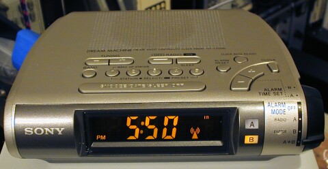
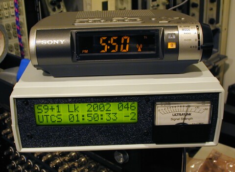
Below is a "atomic time" AM/FM radio alarm clock. This one is made by Sony but there are tens of other brands and models on the market today ranging in price from $19 to $299 [1]. WWVB radio clocks made in the 1990's tended to use an external antenna while more recent units, made since 2000, tend to use a more sensitive internal antenna [2]. I find that for WWVB hobby use the clocks with external antennas are more convenient since the antenna module can be removed for stand-alone use.
The Sony "Dream Machine" FM/AM radio controlled clock radio looks like this:
WWVB radio clocks are regular quartz clocks with a special 60 kHz very long wave (VLF) "radio" capable of receiving the time code signal from radio station WWVB in Ft. Collins, Colorado. Typically the radio turns on only once or a few times every 24 hours, usually at night when reception at this wavelength is best.
The time you see is the time generated by the quartz clock; the radio signals are used only to correct the time displayed by the quartz clock. Strictly speaking then, these are not really "atomic clocks"; they are more appropriately called self-adjusting clocks, or atomic time radio controlled quartz clocks, or periodically adjusted clocks. But I digress.
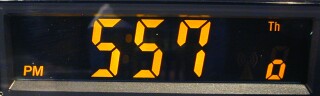
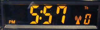
Most models have an icon that indicates if the receiver is operating, or the strength of the reception, or quality of the signal. The Sony is nice in that the zero on the lower right of the display changes shape as the receiver decodes a "0" or a "1" bit. The display flashing during reception and the "O" changes to "o" for each bit received. When reception is good the sequence of O's changes at a 1 Hz rate:
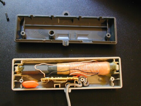
Since it's a Sony (no snaps, no glue, no tape) you are 5 screws away from opening the unit. Here's a look at the external antenna and a view of the inside:
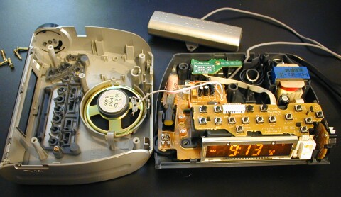
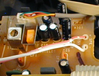
The 4-wire (green-yellow-red-brown) antenna cable is attached to the motherboard with a nice connector. I found that brown is ground; red is +4.4 VDC, yellow is time code output, and green is unused.
Three screws later and the external antenna module is open. The antenna module is not just a ferrite rod with a coil of wire - it also includes a very sensitive specially designed VLF receiver IC. In this module we find a 3 inch ferrite rod with wraps of wire and capacitor chosen to create a 60 kHz L-C resonator:
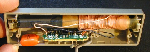
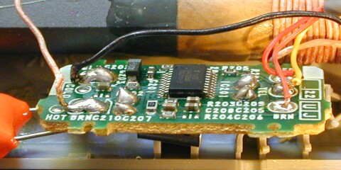
Here's a view of the front and back side of PCB:
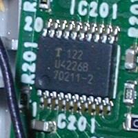
And a close-up of the Temic U4226B 60 kHz time code receiver chip:
Top of PCB showing receiver IC and passive components:
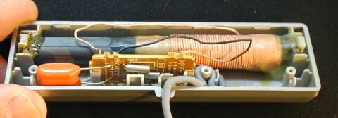
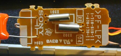
Bottom of PCB showing dual crystal filters:
The time code output waveforms shown later were obtained with an oscilloscope probe connected to the yellow lead:
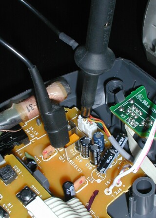
Clock sitting on top of commercial laboratory WWVB receiver [3] to check signal strength:
A final photo before we get to work on waveforms:
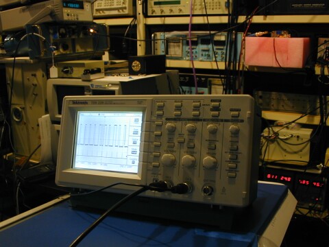
The following three 'scope plots were obtained by connecting the antenna module subcode output (yellow wire in this particular clock) to channel 1 and setting the horizontal sweep time to 1.0 second per division.
| Poor reception: either the time code signal is a flat line, the pulses are erratic, or they occur more often than once per second. |
 |
| Another example of poor reception: erratic and missing pulses. |
 |
Orienting the antenna module perpendicular with a line toward Colorado and moving it closer to the window (and further away from interference such as lamps, PC's, CRT's, and other such electronics) we have an example of very good reception. There is exactly one pulse per second and you can see the pulse width is one of short, medium, or long.
| Good reception: one pulse per second. Pulse width is 200, 500, or 800 ms. |
 |
WWVB transfers a digital serial time code at the data rate of 1 Hz. The 60 kHz carrier power is reduced by 10 dB for a fraction of a second at the beginning of each UTC second. The duration of the reduced power determines the datum: a "0" bit is transmitted by reducing power for 200 ms and a "1" bit by reducing power by 500 ms. To aid in frame synchronization a position marker is transmitted by reducing power for 800 ms. There is one position marker every 10 seconds and two back-to-back position markers at the end of each minute.
So a snapshot of the WWVB time code signal under perfect reception looks like a series of 0.2, 0.5, and 0.8 second pulses at a 1 Hz rate. Note that antenna modules I've played with output a logic low voltage when the WWVB signal is at its normal full power and a logic high voltage when carrier power is reduced.
All the remaining 'scope plots will include a UTC 1 PPS reference marker in channel 2.
| WWVB time code (channel 1) showing 200, 500, 800 ms pulses aligned to UTC (channel 2). The antenna module signal is low for normal carrier power and high for reduced carrier power. |
 |
The following three plots show detail of the typical reception of each type of bit:
| WWVB "0" bit - 200 ms wide |
 |
| WWVB "1" bit - 500 ms wide |
 |
| WWVB "position marker" - 800 ms wide |
 |
In all these 'scope plots channel 2 is a precise 1 PPS pulse synchronized to UTC. We see in the above three bit plots that the rising edge of the WWVB receiver time code output is delayed by some tens of milliseconds from a true UTC seconds pulse. There are two factors contributing to this. First, my lab is located near Seattle, WA, which is close to 1000 miles from Ft. Collins, CO where WWVB is broadcast so there is a 5 ms speed-of-light delay in the signal. The greater contribution in the delay, however, is the receiver's own time constant where it monitors the AGC to determine when a change in power level has occurred.
The pulses on channel 2 are an exact 1 PPS generated by a Cesium clock in my lab. For the purposes of making these plots almost any good on-time 1 PPS source will do, including OCXO, GPS, or a WWVB disciplined receiver.
| In this 30 second composite plot we see the rising edge of the antenna module varies from about 50 ms to 80 ms after the UTC second. I am located 1000 miles from Ft Collins which is about 5 ms; the rest of the delay must be due to the receiver. |
 |
| In this composite plot, we see rising and falling edges occurring primarily at 50 ms + 0, 0.2, 0.5, and 0.8 seconds. Even though this was taken under good reception conditions there is noticeable jitter on both rising and falling edges. |
 |
| Two marker pulses proceed the top of the minute.. FIX |
 |