I've been testing some TCXO (Temperature Compensated Crystal Oscillator) recently. These 14-pin DIP sized, hermetically sealed, metal can oscillators lack a coarse frequency adjustment but they do have an EFC (Electronic Frequency Control) input which makes them suitable for use in a GPSDO (GPS Disciplined Oscillator).
The EFC input is approximately linear. Today we measure how well the EFC input works and see how consistent the four units are.
The following plots were made by varying the EFC input from 0.5 V to 4.5 V in 5 mV steps and measuring the average frequency output at each step.
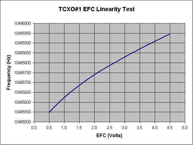
The first plot shows us three things immediately: the EFC is positive (an increase in EFC voltage results in an increase in frequency, the EFC is essentially linear, and on closer inspection, we can see it is not quite linear. This is evidence of the expected non-linearity that most crystal EFC exhibit. Following is the plot:

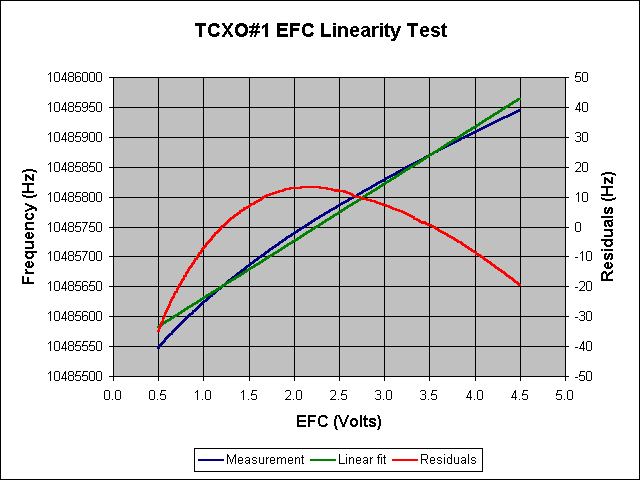
We can see that the full 4 V range of the EFC changes the frequency by about 400 Hz. If we calculate a linear fit to this data we get a slope of 95.44 Hz/V for the EFC gain. Following is a plot of the EFC curve with the best fit line (left axis) and the residuals (right axis):

A summary of the data so far is:
TCXO #1 EFC data set:
count: 801.000000
min: 0.500000 V
max: 4.500000 V
range: 4.000000 V
mean: 2.500000 V
std_dev: 1.156865 V
Frequency data set:
count: 801.000000
min: 10485547.083000 Hz
max: 10485944.427000 Hz
range: 397.344000 Hz
mean: 10485773.032057 Hz
std_dev: 111.032583 Hz
EFC slope:
slope: 95.442681 Hz/V
offset: 10485534.425355 Hz
chi_square: 0.988895
Frequency residuals output:
count: 801.000000
min: -3.506370e+001 Hz (resid)
max: 13.304613 Hz (resid)
range: 48.368309 Hz (resid)
mean: -6.436706e-009 Hz (resid)
std_dev: 11.700834 Hz (resid)
|
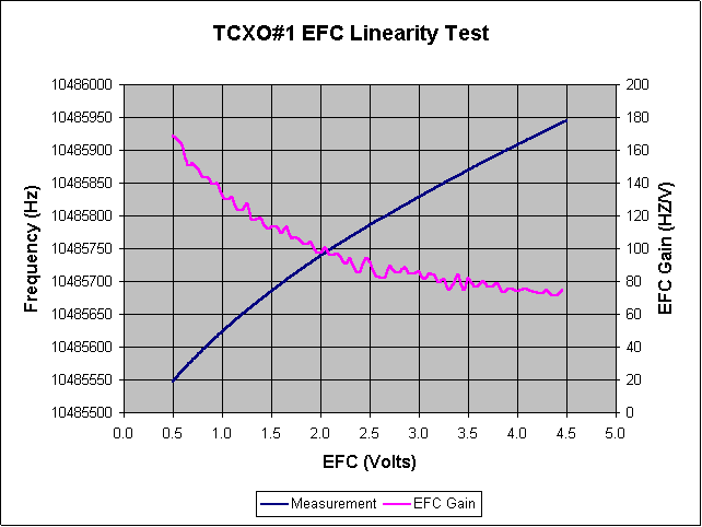
If one assumes a linear, 95 Hz/V model for the EFC it's clear the fit is good but not perfect. Following is a plot of the EFC gain as a function of voltage. For example, if a DAC were to be used to set the EFC one would not want to assume the EFC gain was always 95 Hz/V. In fact the gain varies from about 170 Hz/V down to 70 Hz/V as shown in the following plot:

If this amount of EFC gain variation is too great for the application there are a couple of solutions. One is to note that although the gain varies by 2-to-1 across the range of allowable EFC the variation across 1 volt of center is less than 20 Hz. The other is to use a higher order fit to the EFC curve. Assuming aging and environment permit a second or third order polynomial could be used. The following table shows the decrease in standard deviation for the residuals for successive orders of fit:
| Order | Std. Dev. | Offset | Slope | x^2 | x^3 |
| 0 | 111.03 | 10485773 | |||
| 1 | 11.70 | 10485534 | 95.44 | ||
| 2 | 2.96 | 10485487 | 142.75 | -9.463 | |
| 3 | 0.67 | 10485465 | 181.51 | -27.246 | 2.3710 |
I would guess it is safe to use a 2nd order fit but I would be hesitant to use higher orders than than unless I checked a variety of units, in different environments, over time.
Raw data for the other three oscillators are:
TCXO #2 Frequency data set:
count: 801.000000
min: 10485469.237000 Hz
max: 10485971.523000 Hz
range: 502.286000 Hz
mean: 10485751.168557 Hz
std_dev: 141.440340 Hz
EFC slope:
slope: 121.736623 Hz/V
offset: 10485446.827000 Hz
chi_square: 0.991429
Frequency residuals output:
count: 801.000000
min: -3.845831e+001 Hz (resid)
max: 14.384599 Hz (resid)
range: 52.842910 Hz (resid)
mean: -1.095031e-008 Hz (resid)
std_dev: 13.094598 Hz (resid)
|
A summary of the data so far is:
TCXO #3 Frequency data set:
count: 801.000000
min: 10485501.765000 Hz
max: 10485962.266000 Hz
range: 460.501000 Hz
mean: 10485760.965471 Hz
std_dev: 129.112663 Hz
EFC slope:
slope: 111.086979 Hz/V
offset: 10485483.248023 Hz
chi_square: 0.990728
Frequency residuals output:
count: 801.000000
min: -3.702651e+001 Hz (resid)
max: 13.844014 Hz (resid)
range: 50.870527 Hz (resid)
mean: -1.267343e-009 Hz (resid)
std_dev: 12.432650 Hz (resid)
|
A summary of the data so far is:
TCXO #4 Frequency data set:
count: 801.000000
min: 15728294.568000 Hz
max: 15728896.150000 Hz
range: 601.582000 Hz
mean: 15728640.372840 Hz
std_dev: 168.073696 Hz
EFC slope:
slope: 144.326060 Hz/V
offset: 15728279.557691 Hz
chi_square: 0.986860
Frequency residuals output:
count: 801.000000
min: -5.715272e+001 Hz (resid)
max: 21.279675 Hz (resid)
range: 78.432396 Hz (resid)
mean: 3.239282e-009 Hz (resid)
std_dev: 19.266078 Hz (resid)
|
Notice that the three 10.48576 MHz oscillators have quite different curves: 95, 111, 121 Hz/V. The fourth oscillator is 144 Hz/V but it's nominal frequency is 15.72864 MHz which is the equivalent of 96 Hz/V if it were 10.4 MHz like the other three.
The following are frequency normalized plots (so that all four oscillators are represented):
I ran the EFC gain experiment on the same oscillator ten times to see how consistent the curve was for a given oscillator.
This experiment was done using a SR 620 counter controlled by a PC over RS-232. This counter has a software programmable DAC allowing voltages from 0.5 V to 4.5 V in 5 mV steps to be created. The program alternated setting the DAC and taking multiple, averaged, frequency readings. I used either 100 10 ms measurements or 10 100 ms measurements. After 801 steps the full EFC range is covered.
The program to control the SR 620 is: com620b.exe
The program to analyze the data is: efc1.exe
The program to compute polynomial fits is: lsq2.exe