The pP07 was designed for optical sensors of pendulum clocks, where both the time and the duration of the pulse is useful. In this case timing both edges gives not only beat / period / symmetry data but also velocity / amplitude data.
A side-effect is that pP06 can make over 100 measurements per second while the pP07 is limited to 40 per second. Thus, pP06 can easily time every cycle of a 50/60 Hz mains frequency, and pp07 can easily measure every edge of a mechanical clock that swings once or twice or ten times a second.
;                                ---__---
;                5V (Vdd)  +++++|1      8|=====  Ground (Vss)
;            10 MHz input  ---->|2  pP  7|<+---  Rise(1) Fall(0) edge
;            RS232 output  <----|3  06  6|<+---  Zero-sync(0)
;         RS232(0) TTL(1)  o--->|4      5|<----  Event pulse input
;                                --------
;
;                                ---__---
;                5V (Vdd)  +++++|1      8|=====  Ground (Vss)
;            10 MHz input  ---->|2  pP  7|<+---  Pos(1) Neg(0) pulse
;            RS232 output  <----|3  07  6|<+---  Zero-sync(0)
;         RS232(0) TTL(1)  o--->|4      5|<----  Event pulse input
;                                --------
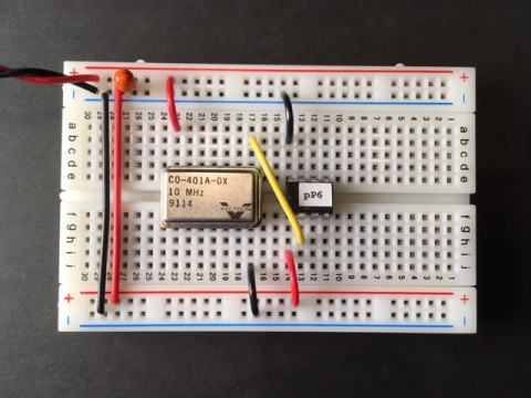
Example 14-pin DIP sized 10 MHz CMOS oscillator:
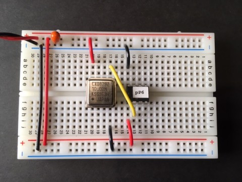
Example 8-pin DIP half-sized 10 MHz CMOS oscillator:
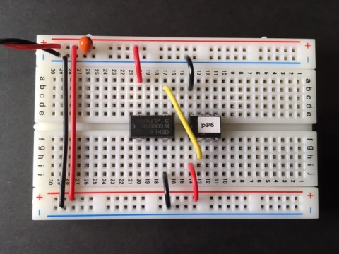
Example 8-pin plastic DIP 10 MHz oscillator:
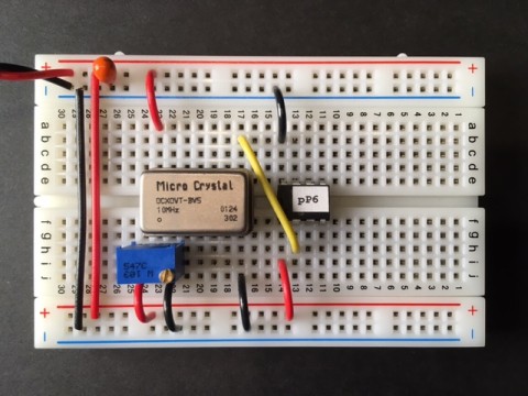
Example 14-pin DIP sized 10 MHz OCXO oscillator with fine frequency adjust. CW to increase frequency:
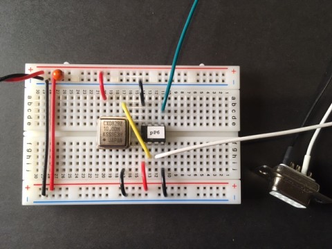
Doing direct drive 5 V RS232, DE9S connector. Note the black wire (ground) to pin4:
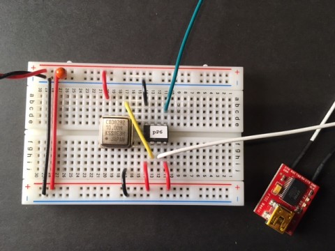
Using FTDI serial/USB converter. Note the red wire (5 V) to pin4:
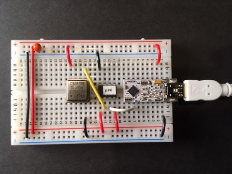
Using onboard DIP FTDI serial/USB converter for output and for 5 V power. Self-powered, very convenient:
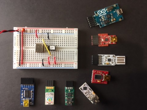
Wide selection of FTDI-based serial/USB converters:
;                                ---__---
;                5V (Vdd)  +++++|1      8|=====  Ground (Vss)
;            10 MHz input  ---->|2  pP  7|<+---  Rise(1) Fall(0) edge
;            RS232 output  <----|3  06  6|<+---  Zero-sync(0)
;         RS232(0) TTL(1)  o--->|4      5|<----  Event pulse input
;                                --------
;
;   - GP0/pin7 (WPU) selects trigger edge. Leave high for rising edge.
;     Pull to ground for falling edge.
;     Note the pin is re-read every event (allows dynamic edge selection).
;
;   - GP1/pin6 (WPU) allows optional counter clear or 1PPS synchronization.
;     Pull to ground and next event will reset time-stamp to zero.
;
;   - GP2/pin5 is event input (Schmitt trigger).
;
;   - GP3/pin4 controls serial output polarity. Ground for normal "true"
;     unipolar RS232. Set high for "inverted" serial (TTL, MAX232, FTDI).
;     Microchip says do not leave this pin floating.
;
;   - GP4/pin3 is serial output, 19200 baud.
;
;   - GP5/pin2 is clean precise digital 10 MHz clock input.
;
;   - Vdd may be 2.0 to 5.5 VDC. See PIC 12F675 datasheet for details.
;
;                                ---__---
;                5V (Vdd)  +++++|1      8|=====  Ground (Vss)
;            10 MHz input  ---->|2  pP  7|<+---  Pos(1) Neg(0) pulse
;            RS232 output  <----|3  07  6|<+---  Zero-sync(0)
;         RS232(0) TTL(1)  o--->|4      5|<----  Event pulse input
;                                --------
;
;   - GP0/pin7 (WPU) configures pulse polarity. Leave high for positive pulse
;     (low-high-low). Pull to ground for negative pulse (high-low-high).
;     Note the pin is read once only at power-up.
;
;   - GP1/pin6 (WPU) allows optional counter clear or 1PPS synchronization.
;     Pull to ground and next event will reset time-stamp to zero.
;
;   - GP2/pin5 is event input (Schmitt trigger).
;
;   - GP3/pin4 controls serial output polarity. Ground for normal "true"
;     unipolar RS232. Set high for "inverted" serial (TTL, MAX232, FTDI).
;     Microchip says do not leave this pin floating.
;
;   - GP4/pin3 is serial output, 19200 baud.
;
;   - GP5/pin2 is clean precise digital 10 MHz clock input.
;
;   - Vdd may be 2.0 to 5.5 VDC. See PIC 12F675 datasheet for details.
# picPET: 06.10
00.0000000 01
00.0166788 02
00.0333420 03
00.0500044 04
00.0666492 05
00.0833104 06
00.0999380 07
00.1165504 08
00.1331900 09
00.1498044 0A
00.1664212 0B
00.1830688 0C
00.1997620 0D
00.2164468 0E
00.2331748 0F
00.2498592 10
00.2665568 11
00.2832676 12
00.2999828 13
00.3166940 14
00.3333676 15
00.3500728 16
00.3667348 17
00.3833764 18
00.4000556 19
00.4166680 1A
00.4332960 1B
00.4499360 1C
00.4665692 1D
00.4832100 1E
00.4998740 1F
00.5165348 20
00000.0000000 8F 00000.1000020
00001.0000000 90 00001.1000020
00002.0000000 91 00002.1000016
00003.0000000 92 00003.1000016
00004.0000000 93 00004.1000016
00005.0000000 94 00005.1000016
00006.0000000 95 00006.1000016
00007.0000000 96 00007.1000016
00008.0000000 97 00008.1000016
00008.9999996 98 00009.1000016
00009.9999996 99 00010.1000016
00010.9999996 9A 00011.1000012
00011.9999996 9B 00012.1000012
00012.9999996 9C 00013.1000012
00013.9999996 9D 00014.1000012
00014.9999996 9E 00015.1000012
00015.9999996 9F 00016.1000012
00016.9999996 A0 00017.1000012
00017.9999992 A1 00018.1000012
00018.9999992 A2 00019.1000012
00019.9999992 A3 00020.1000012
# picPET: 06.10
00.0000000 01
00.4949496 02
01.0169780 03
01.5119608 04
02.0337836 05
02.5285804 06
03.0507184 07
03.5455264 08
04.0676596 09
04.5624472 0A
05.0845980 0B
05.5793864 0C
06.1015296 0D
06.5963128 0E
07.1184292 0F
07.6132052 10
08.1353200 11
08.6300848 12
09.1520940 13
09.6470832 14
10.1690180 15
# picPET: 07.02
00000.0000000 01 00000.0113072
00000.4949496 02 00000.5062688
00001.0169780 03 00001.0282884
00001.5119608 04 00001.5232800
00002.0337836 05 00002.0451048
00002.5285804 06 00002.5399224
00003.0507184 07 00003.0620460
00003.5455264 08 00003.5568676
00004.0676596 09 00004.0789980
00004.5624472 0A 00004.5737984
00005.0845980 0B 00005.0959408
00005.5793864 0C 00005.5907388
00006.1015296 0D 00006.1128780
00006.5963128 0E 00006.6076772
00007.1184292 0F 00007.1297820
00007.6132052 10 00007.6245696
00008.1353200 11 00008.1466828
00008.6300848 12 00008.6414532
00009.1520940 13 00009.1634660
00009.6470832 14 00009.6584724
00010.1690180 15 00010.1804060
# picPET: 07.10
00000.0000000 01 00000.0039600
00000.0318448 03 00000.0379152
00000.0650908 05 00000.0710896
00000.0982504 07 00000.1048080
00000.1312372 09 00000.1384664
00000.1647936 0B 00000.1717396
00000.1978300 0D 00000.2054744
00000.2310472 0F 00000.2388984
00000.2644380 11 00000.2722160
00000.2977684 13 00000.3055760
00000.3311816 15 00000.3388792
00000.3645828 17 00000.3722152
00000.3979388 19 00000.4055180
00000.4312628 1B 00000.4388780
00000.4646556 1D 00000.4722456
00000.4979680 1F 00000.5056388
00000.5312848 21 00000.5389576
00000.5646636 23 00000.5723496
00000.5979800 25 00000.6056860
00000.6313640 27 00000.6390064
00000.6647520 29 00000.6723152
00000.6980700 2B 00000.7056976
00000.7314220 2D 00000.7390552
00000.7647776 2F 00000.7724284
00000.7980812 31 00000.8057904
00000.8314628 33 00000.8391716
00000.8647996 35 00000.8725112
00000.8981880 37 00000.9058232
00000.9315732 39 00000.9391580
00000.9649684 3B 00000.9724696
00000.9983312 3D 00001.0058016
00001.0316764 3F 00001.0391332
00001.0650484 41 00001.0724776
The above example accidentally demonstrates the ability to make precise frequency or period measurements over a wider range of frequency than the normal data rate of the picPET. That is, one does not necessarily need a timestamp of each and every cycle. Instead they key is to have precise timings of some cycles along with a precise count of all cycles. Linear regression can then be performed on the set of { time tag, cycle count } pairs. This method is considerably more versatile and accurate than traditional "gated" frequency measurements.
In this scenario, the event rate (frequency) limit for pP06 is about 28 kHz, which is the point where more than 256 events occur between 110 timestamps per second. If higher rates are needed a simple external prescaler can be used.
/tvb